
Diagram
Fixed configuration
The 'physical' aspects of KNX Virtual are fixed, which means that no areas, no lines, no segments and no devices can be added, moved or removed.
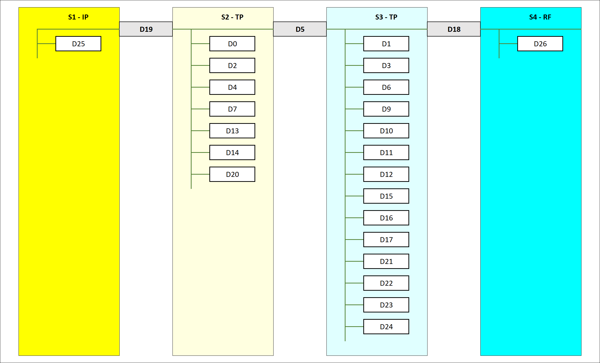
Topology = 4 segments
KNX Virtual v2.5 represents a KNX installation consisting out of 4 segments:
- 1 IP segment : represented as 'S1'
- 2 TP segments : represented as 'S2' and 'S3'
- 1 RF segment : represented as 'S4'
The 4 segments are concatenated as follows:
- S1 is connected to S2 via device D19, which is an IP/TP coupler (or short 'IP coupler')
- S2 is connected to S3 via device D5, which is a TP/TP coupler (or short 'TP coupler')
- S3 is connected to S4 via device D18, which is a TP/RF coupler (or short 'RF coupler')
Interface
KNX Virtual has one tunneling interface:
- Represented by device D20, which is an IP/TP interface (or short 'IP interface')
- D20 is hosted by device D19
- D20 is connected to segment S2
- D20 has a fixed individual address: 1.0.255
Since the individual address of the interface is fixed to 1.0.255:
- The area of the installation is fixed to 1
- The line address of any device connected to S2 is fixed to 1.0
Topology variants
3 possible topology variants can be configured:
|
S1 |
D19 (*) |
S2 |
D5 (*) |
S3 |
D18 (*) |
S4 |
|
|
variant 1
|
0.0
|
1.0.0 backbone coupler |
1.0
|
1.x.0 line coupler |
1.x
|
1.x.y segment coupler |
1.x
|
|
variant 2
|
0.0
|
1.0.0 backbone coupler |
1.0
|
1.0.x segment coupler |
not supported by ETS |
||
|
variant 3
|
1.0
|
1.0.x segment coupler |
not supported by ETS |
||||
(*) x > 0, y > 0 and z > 0
Notes:
- A segment coupler is always the 'lowest' coupler in regards of hierarchical order, this is the reason why S4 is not supported by ETS in variant 2 and why S3 + S4 are not supported by in ETS in variant 3
- For both projects the password is:
a
- For both projects the password is:
- The ETS projects for variant 2 ('D5_segment_coupler') and variant 3 ('D19_segment_coupler') are attached to this article, an example project for variant 1 can be found here